300x250 AD TOP

Search This Blog

Pages

Paling Dilihat

Powered by Blogger.

Tuesday, June 27, 2017

RTK Rover and Base Configuration Web Interface

So I've been working on this for the past few weeks


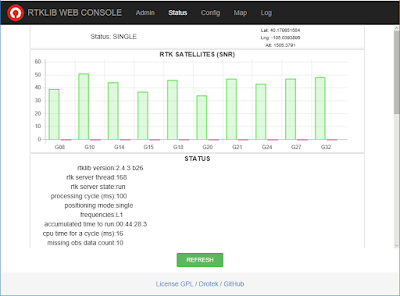
When I first started to mess around with RTKLIB I've wanted to have a nice UI to do that, while researching it I came across a product from drotek.com which already has a nice UI and I was glad to find its an open source (!!).


So I decided to sit down and take a look at it, at first I was a little dissapointed to see it worked on Intel Edison Only as I didn't find this board particularly interesting and now after reading that Intel discontinued it I think its even more important to find generic SBCs.

So I started to dig in the source code and I was glad to find out its written in Node Js as Node was one of my primary development environments for the past couple of years. I went over the source code and it seemed simple enough to work on, so I npm install 'ed it and went to work.

First, I've converted the whole project to typescript and cleaned up some Edison specific code, then I went ahead and ported rtkrcv to windows but since windows doesn't have a tty console, I've decided to disable that functionality and worked on making the tcp console work. I also wanted this project to work on M8N so I've had to upgrade rtklib to 2.4.3 as well., I've found a bug or two and went ahead to create an web interface for the services.

I've added loggers, PM2 and split the str2str and rtkrcv to their own hosted services so I've had better control over the service lifecycle and the ability to monitor it in realtime in any way possible, so monitoring console output for errors, monitoring logs for messages to be exposed as events and monitor rtkrcv monitor port and control port to get even more useful information, such as streams statistics, satellites, observations, navigation data and ofcurse the latest position and SNR and exposed all that information as APIs.

In the UI, I've converted the project to typescript which helped me to clean up a few issues, add a toastr for better error reporting, add socket.io to get realtime notifications and implemented a periodic update of all the statistics I wanted as well as add the ability for the station to work as both base and rover, which in essence means it can start str2str and rtkrcv and have complete control over the inputs and outputs. I've even added a com port detection API for the UI.


I've updated the chart.js version to get better animation for the satellite SNR graphs and added a finer resolution in the Map section.


For the rtkrcv and str2str I've added a gyp build configuration so it can be compiled in almost any environment, so far I've tested it on Windows, Linux x64 and Linux Arm and seems to be working without a hitch even on Orange PI Zero.

Now, I'll probably start testing it in a small scale, originally I wanted it for my Rover project, but this project was a learning experience as well as fun.

I'm looking for someone else to take over this project, I see great potential for it to be used across the navigation hobbyist community.

https://github.com/drorgl/SMARTNAV-RTK
Tags: , , , ,

Wednesday, June 21, 2017

Emulating COM Ports on Windows

My computer is not near a window, but I do need to get data from my GPS to RTKLIB hosting program I'm rebuilding.

So after trying a long wire, a wireless relay and even going outside, I've decided to try a COM port emulation solution.

After looking around I've found an old unsigned driver of com0com, but since its not signed, its a hassle to install and I don't really want to open up my computer to these kinds of security risks.

After looking around I've found a signed version at  https://code.google.com/archive/p/powersdr-iq/downloads

Once I've installed the driver, I have access to com0com setup

Basically, you'll need to mark the class checkbox and it will become just like a regular com port.


After that, you should download the com port data generator from aggsoft


Although you can generate random data, its best to use real data recorded previously, if you're interested in RTK GPS data, you can download the raw bytes from rtkexplorer.


Once you start playback, you can attach the appropriate RTKLIB application to the 2nd com port and see how its doing


Tags: , ,

Saturday, June 17, 2017

Powering Orange PI Zero with a Power Bank

You might ask yourself why wouldn't it work?
I asked myself the same question when I saw the tiny thing won't turn on, or worse, turn on and freeze all the time.

The answer lies in the way power banks work and some of the power converters, as well as usb power supplies.

In the good old days when you wanted to take a power source like 220v or 110v and down convert it to 5v, you would use a transformer, then a rectifier and lastly filter out the noise with a capacitor and optionally an inductor. This works great and if used on audio applications the noise is inaudible or very close to it (at least not from the power source) but the biggest drawback of this method is weight, high power transformers weight a lot.

These days there is a need to make things smaller and weight less and so we have all sorts of switching power supplies and as their name implies, they switch the power on and off to achieve the same goal.

In general there are 3 types of switching power supplies:
- step-up, also referred to as boost converters where the input voltage is lower than the output.
- step-down, also referred to as buck converters where the input voltage is higher than the output.
- buck-boost converters where the input voltage can either be lower or higher.

In my particular case it is step-up converter from a Lithium Ion battery so 3.7v - 4.2v up to 5v


But lets look how bad it is


If you look at the ripple size, it pretty much covers the whole voltage output range, a very fast ripple but still.

Looking at the Orange PI Zero, there seem to be another relatively large inductor next to the USB connector where power comes in:


Which led me to believe another type of switching is going on the PI and common sense dictactates that two switching power supplies without some type of smoothing or filtering is a bad idea.

So I decided to experiment with a small 220uf capacitor and solder it straight on the power bank


And voilĂ  !


124mv !


But the best part is, its actually working and stable.

Tags: , ,

Friday, June 16, 2017

OpenSprinkler using ESP8266

"If necessity is the mother of invention, then laziness is the father." - attributed to Allen Dale

Sometime ago I've read about OpenSprinkler (source code) and I had to try it, I was a bit dissapointed when first I saw it worked on Raspberry PI Zero, but then I saw other boards it might work on, until I've found a port to ESP8266 and decided to give it a go, but I should also note there's an official ESP8266 OpenSprinkler with Source Code.

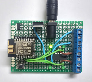
The design I chose to start with is pretty primitive, I didn't want any LCD or RTC, ESP8266 can get the time though NTP so I didn't see much use to it, for the solenoid drive I chose L293D, which should be more than enough for home valves with 600ma output (and 1.2A for peak current).

Throw in some terminals, a few leds, a pcb and a voltage regulator and you have a working prototype.

Which ESP8266 you ask? there are so many, if you need less than 8 stations, you can use the cheaper ones for about $2.

Just remember to modify the pins used for each station, put a mosfet or a driver between the MCU, the pins are configurable through Pins.h under PIN_STN_S01 - 16 (on board with more pins, the version I have, has only 8).

When I first tried to build OpenSprinkler I've encountered a few issues, first, I had a very old NewLiquidCrystal library, which doesn't work on ESP8266, trying do download a new version through downloads doesn't solve the problem because its not there, you'll need to download either through Download Repository or through Mercuial clone.

After fixing that problem, I've started to configure the build to my needs, I've fixed the OPENSPRINKLER_ARDUINO_FREEMEM flag so it will report how much memory is available, I've reduced the number of stations to 4, changed the location and remove the default NTP IP since it wasn't working.

To save some water its recommended you get your own weather key from weather underground. the developer key is sufficient for getting your prototype going but you will most definitely need a commercial key if you're planning to sell it.

I've also found a few problems with WifiManager, it seems the development was not complete, so I've added the debug messages, a reset command, renamed the AP name and finally add ESP.eraseConfig and dump ESP info into the debug log.

Another modification I made was to remove all the unneeded buttons since it was mostly needed for the LCD, I did add one button so when the board starts with the button pressed it will reset all setting to defaults.


A few things about this build:

- Voltage regulator - I didn't have a 3.3v voltage regulator that could work on 12v, I've had to get it down to 5v (with 7805) and then again to 3.3v (with A1117).

- ESP8266 does have a breakout board, I didn't have one available so I decided to solder it straight on some pins.


Now for the fun part, testing it :-)

Source - https://github.com/drorgl/OpenESP8266_Sprinkler/tree/ModAfterUpload/OpenSprinkler_Arduino_V_2_1_6

Tags: ,